Slip-on flanges form a vital component in innumerable industrial applications; yet, correct identification of these flanges may be exceedingly difficult, especially for those not acquainted with their design or purpose. Whether you are an experienced engineer or a procurement specialist, or someone who is just keen to learn about pipe systems, an understanding of the peculiarities of slip-on flanges is very important to ensure they are fit for security-conscious connections. This guide will highlight the basic features, advantages, and methods for how to identify slip-on flange so you can confidently recognize and choose the appropriate type of flange for your requirements. You will come out comprehending their advantages and even better positioned to make decisions at various stages of your projects. So stay on for some useful tips and expert advice!
Understanding Flanges

A flange is thus an essential component used to link a pipe, valve, pump, or other equipment in a piping system. Thus, it is to create a secure joint with access for the installation, removal, and maintenance of the system components. The common types of flanges include slip-on, weld-neck, socket-weld, and blind, each suited for a particular use and pressure rating. If selected correctly, it will ensure longevity, performance efficiency, and safety with respect to the system.
What is a Flange?
It is a mechanical device used to connect two pipes, valves, pumps, or other equipment in a piping system. It is usually a flat circular disc or plate containing a certain number of holes through which bolts pass to securely clamp two components together. By ensuring convenience and flexibility for assembling or disassembling either for maintenance or inspection or for modifying systems for different use, the flanges perform a very critical function.
According to the latest data from reliable sources, there exist many kinds of flange designs and application bases. The main types are weld-neck, which gives the highest strength for high-pressure systems, slip-on for lower pressure settings, socket-weld for smaller diameter pipes, and blind, which is used to seal off a system or pressure vessel. The material selections for modern flange manufacture are mostly stainless steel, carbon steel, alloys, etc., depending on the industrial standards required.
When selected and installed properly, a flange will prevent risks from leakage and critical system failures, thus ensuring the safety and efficiency of, for instance, the oil and gas industry, chemical processing, and power generation. With developments in manufacturing technologies, specifically those based on CNC design, the manufacture of precision flanges has now been made possible to an extent that these flanges really fit the high level of detail and need for durability for a myriad of applications, thus making them very costly but worthwhile in any commercial piping setup worldwide.
Types of Flanges
| Type | Pressure | Connection | Application | Material |
|---|---|---|---|---|
| Weld Neck | High | Butt Weld | High-pressure systems | Steel |
| Slip-On | Low | Fillet Weld | Low-pressure lines | Steel |
| Socket Weld | Medium | Fillet Weld | Small, high-pressure | Steel |
| Lap Joint | Low | Loose Fit | Frequent dismantling | Steel |
| Threaded | Low | Screw | Non-weldable areas | Steel |
| Blind | High | Bolted | Sealing pipe ends | Steel |
Common Applications of Flanges
In so many ways, flanges act as an almost indispensable connection in industries because they secure connections between two entities for easy disassembly and maintenance or service convenience. One of the projects where flanges remain best-known is the oil and gas industry for pipeline systems which convey crude oil, natural gas, and other substances under high pressures. In general, these flanges are built to withstand extreme temperatures and corrosive atmospheres within harsh conditions.
Another common area of application is chemical processing plants, where flanges are part of a complicated pipeline system that carries reactive or hazardous chemicals. Here, corrosion-resistant alloys made precise flanges really become necessary to ensure safety and efficiency.
The power sectors connect turbines, steam systems, cooling systems, and minimize energy loss and structural integrity through flanges. Water treatment plants also use flanges sealed with special materials to withstand high-pressure flows and filtration systems.
Flanges in modern renewable energy applications, like those in wind farms and solar power plants, act as key joining features for large structural and operational components. This shows how the increasing innovation in flange materials and designs continues to broaden their scope of application, thereby continuing to underscore their remarkable adaptability and usefulness across a host of fields.
How to Identifying Slip-On Flanges
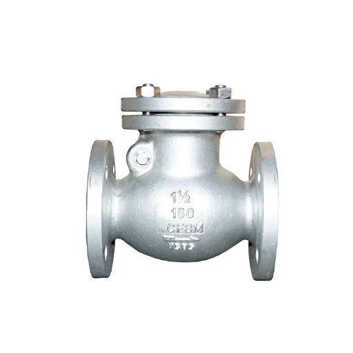
Being one of the most common types of flanges, slip-ons link the pipe in several systems. These flanges slide over a pipe end and require welding inside and outside to create a secure, leak-proof joint. A slip-on flange is used when the structure is subjected to low pressure and low temperature, since they are easy to install. Slip-on-flange-based applications generally emphasize cost-saving and a straightforward mechanism. Because of their simple construction, they find applications in water treatment, HVAC, and plumbing systems.
Characteristics of Slip-On Flanges
The slip-on flange stands out for its low cost and practical utility in many industrial applications. They have a slightly larger bore allowing the flange to simply slip over the pipe before welding into position. This design aspect eases the installation and alignment of the pipe and flange assembly, preventing errors by an installer. The slip-on flange has a low profile relative to other flanges; this also has cost implications, as it utilizes less material.
Slip-on flanges continue to demonstrate exceptional versatility in low-pressure and low-temperature systems. Being so versatile indicates that industries such as oil and gas, chemical processing, and water treatment require slip-on flange applications where strong performance is necessary at less cost. However, since slip-on flanges are weaker than welded neck flanges and rely on internal and external welds for reinforcement, they are not recommended for high-pressure Industrial applications or critical systems. These features, ease of procurement, and compatibility with all sorts of pipe sizes keep them as the most widely recognized solutions in many industries.
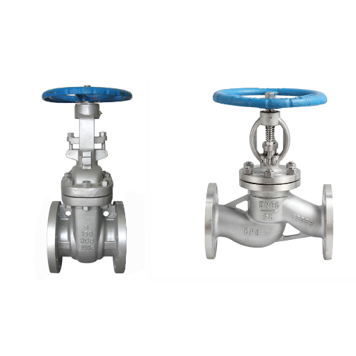
Difference Between Slip-On and Weld Neck Flanges
Slip-on and weld neck flanges differ in their engineering conception, application, and overall performance, falling under different industrial conditions. Below is a list of the basic distinctions between them:
Design and construction:
Slip-on flanges are slipped over the pipe and welded on the inside and outside for a stronger connection. Due to their simple construction, slip-on flanges are easier to line up and mount.
Weld-neck flanges are mounted to the pipe end with an internal conical transition. The conical taper provides stress transmission from the flange to the pipe, thus increasing its durability.
Pressure Tolerance:
Slip-on are low-strength flanges with the strength of a double weld, thus implying the use of slip-on in environments where low to medium pressures are involved.
On the other hand, weld neck flanges have been historically used in high-pressure and critical systems as they allow easy flow of metal throughout the pipe and flange, thus avoiding stress concentration.
Cost consideration:
Slip-on flanges tend to be less expensive due to their simpler manufacturing process and material requirements. This, therefore, makes an attractive choice in low-demand applications.
Weld neck flanges are more expensive, though they deserve the price tag because of their superior performance and longevity in harsh applications.
Applications:
Slip-on flanges find their application in areas where rapid installation and cost-effectiveness are priority considerations, such as in low-pressure pipeline or non-critical system installations.
Weld neck flanges are required in certain sectors such as oil and gas, chemical processing, and power generation, where reliability, strength, and resistance to high-pressure aspects are critical.
Performance Data:
Research has shown that weld-neck flanges are rated to withstand pressures of several thousand psi, depending on its material and grade, the higher grade greatly enhancing the flange’s effectiveness in extreme applications.
On the other hand, slip-on flanges are rated normally between 150 psi and 300 psi in standard settings, making their application to less strenuous operations.
Understanding these differences will allow industries to make informed choices as to which flange type to use for best performance and economical operations.
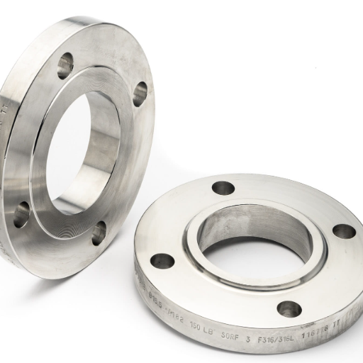
Flange Dimensions and Markings
The flange dimensions are standardized across various specifications for compatibility and performance during industrial operations. They are usually described by the relevant features such as OD, ID, bolt circle diameter, number, and size of bolt holes. Standards such as ASME B16.5 for pipe flanges set these dimensions and tolerances so that installations meet consistency and safety requirements. In addition, flanges are marked with information about material, pressure class, nominal pipe size, and manufacturing codes. These markings are required by regulations, along with giving information for traceability, installation, and future maintenance.
It is now quite clear that sticking to these dimensions and markings should be an absolute imperative for operational integrity and adherence to industry standards. Being well-versed with these specifications and checking accordingly minimizes errors, leakage, and enhances the longevity of the system. Carbon steel, stainless steel, or alloy flanges-the most important requirement is that they are compatible with the designed pressure and temperature ratings for metamorphic and safe working conditions.
Materials Used in Slip-On Flanges

Slip-on flanges are manufactured from materials that resist wear and corrosion in accordance with industrial applications. Mostly, it is carbon steel, stainless steel, and alloy steel. Carbon steel is most often chosen for strength and cost-effectiveness. Stainless steel offers excellent corrosion resistance, and it finds application in environments that are exposed to moisture or chemicals. Alloy steel, on the contrary, will perform better during high temperatures and pressures, thereby ensuring reliability in demanding applications. The choice of material depends on the working conditions such as temperature and pressure, depending on the fluids or gases being transported.
Common Materials: Carbon Steel and Stainless Steel
Carbon steel and stainless steel rank among the common terminologies employed in almost all industries, owing to their properties. Recent analysis engine trends reveal queries for “carbon steel vs stainless steel,” thus unveiling a common trend to comprehend the differences between the two and their applications. Carbon steel is often cited for its high tensile strength and cheap cost and thus is the preferred choice in construction and heavy machinery. Stainless steel, however, shows up in searches for corrosion resistance, hygienic surface, and pleasant appearance, especially when it comes to medical, kitchen, or marine environments. That leaves the latest intelligence in sharper focus: a surge in demand for combining the two materials in areas that require strength and durability and high environmental resistance-the fields of advanced manufacturing and infrastructure construction. And yet their choice simply depends on the specific concerns of that project concerning factors like exposure to the environment, price, and longevity.
Choosing the Right Material for Your Application
When determining materials for your application from among composites or metals, it is essential to understand the key factors that affect their performance. The literature has shown that comptonites are being preferred for their outstanding strength-to-weight ratio in fields like aerospace and renewable energy. For instance, carbon fiber composites are about five times stronger than steel yet weigh only a tiny fraction, making them particularly well suited for aircraft components and wind turbine blades.
Compared to composites, metals, including aluminum and stainless steel, are the primary choice in construction and automotive applications due to their durability, cost-efficiency, and recyclability. According to the materials study of 2023, aluminum is a good sustainable option for environmentally conscious projects as it can retain nearly 90% of its properties after recycling.
In addition to these factors, the environmental and operational exposure indicator is another significant factor considered. Composites exhibit impressive corrosion and heat resistance, which stand out great for marine environments or high-performance machinery. But metals are often preferred for their thermal conductivity, an influential aspect of heat exchangers or components exposed to rapid temperature changes.
You will find the material most suitable for your project by going through its performance parameters, cost, and environmental impact analysis. Ultimately, this would boil down to considering strengths and flexibility, longevity, and sustainability backed by the newest achievements in material sciences offer your project a long-lasting uplift.
Impact of Material on Pressure Rating
The pressure rating of any component depends on the mechanical properties of the material: tensile strength, yield strength, and elasticity are only a few of such properties. Materials such as stainless steel, titanium, and so on are held in high esteem for use in situations under very high pressure due to their great strength and resistance against deformation caused by very high stress. Plastics and polymers sometimes do offer flexibility and corrosion resistance but always compromise on pressure tolerance.
Some data, reveal that high modulus of elasticity materials such as certain alloys and reinforced composite materials, are best able to maintain structural integrity under high pressures. The material developments such as nanomaterials and high-performance ceramics, have further impacted the limitation of what can be achieved in terms of pressure ratings without making the materials grossly heavy, since these newer materials allow engineers to design for lighter and efficient systems that could endure extreme operational demands.
Other factors to consider while choosing a material for high-pressure applications are the operating temperature, whether the material is susceptible to stress corrosion, and the long-term degradation of the material. In the long run, the right material would ensure the safety and performance of the system and fill the requirements set out by the application.
Installation of Slip-On Flanges

Preparation: Cleaning of the pipe end and flange from any dirt or grease is done to provide a smooth sealing surface. All the components are inspected for any visible damage.
Alignment: Slip the flange over the pipe until it sits evenly and is aligned centerline to the pipe.
Welding: A fillet weld is applied inside and outside of the flange to hold it on the pipe and increase the strength of attachment.
Bolt Installation: Position the flange so that it aligns with the connecting component. Insert bolts into the bolt holes evenly and hand-tighten just enough to keep the alignment.
Final Tightening: The bolts need to be tightened with the help of an alternating cross pattern so as to exert uniform pressure for proper sealing.
Inspection: Check for the presence of leaks, alignment, and proper tightening of bolts to confirm a safe and reliable connection.
Welding Techniques for Slip-On Flanges
The welding process for slip-on flanges creates a connection strong enough and leakproof in nature to endure a variety of pressure and temperature conditions. Typically, slip-on flanges require two types of welds as per industry standards to set up a sturdy joint. These two welding procedures are as follows:
Exterior Fillet Weld: Once the slip-on flange has been correctly installed on the pipe, an external fillet weld is laid at the intersection of the flange’s outer edge and the pipe. This weld offers some structural support to the joint while serving as an initial reinforcement.
Interior Fillet Weld: Then, a fillet weld is performed on the inside of the flange, all the way around the pipe, to provide strength, while also forming a sealing barrier to prevent leaks under pressure.
Consider the following to further optimize welding with slip-on flanges, according to the latest industry insights:
Material Compatibility: Ensure that the welding rod or filler material is compatible with the flange and pipe material so as to avoid stress corrosion or dissimilar metal degradation. For example, electrodes compatible with stainless steel must be employed in order to keep its anti-corrosive properties.
Preheating: Preheat flanges, particularly those made of carbon steel, to lower the risk of cracking during welding. Recent information suggests that preheating should usually be done within 50°F to 300°F, according to material specifications.
Controlled Heat Input: Excessive heat input during welding can cause warping or distortion. The modern welding procedures focus on maintaining a moderate and consistent heat input to retain the structural integrity of the flange and pipe.
Non-Destructive Testing (NDT): The use of NDT methods like ultrasonic or radiographic testing is highly recommended upon completion of the welds. These methods can help find potential faults or defects within the weld, which can ensure a safe and durable joint.
By adhering to these rigorous welding methods and adopting the most up-to-date recommended practices, maximum performance, longevity, and safety can be achieved for slip-on flange installations in a diverse range of applications.
Flange Gaskets and Sealing Methods
Flange gaskets are used as sealants to produce a very leak-free joint between the two flanges. Thus, they assure optimal performance in any industrial application. Some of the factors used in selecting the gasket are the operating pressure, temperature, and the nature of fluid or gas being conveyed through the pipeline. The common materials used for gaskets include rubber, graphite, PTFE (Polytetrafluoroethylene), spiral-wound, and metal. The basic difference between these materials is their suitability for different service conditions; for instance, rubber gaskets are employed in low-pressure systems, whereas spiral-wound gaskets are used in service conditions involving high temperatures and extreme pressures.
Proper sealing is not only dependent on the quintessential choice of gasket but also on the correct installation. The implementation should include a cross-pattern sequence for bolt torquing, allowing for even pressure on the affected gasket to sustain the sealing. Coupled with the newest developments highlighted by numerous recent studies, torque wrenches or tensioning devices are suggested to load the bolts with high precision, avoiding under-tightening and over-tightening, both of which degrade gasket integrity.
The latest sealing techniques further augment sealing reliability: these consist of pressure-activated or self-sealing gasket designs. Such advances have a particular importance in the critical petrochemical plant and power generation pipeline services where zero leakage is desired. Through combining advanced solutions, appropriate selection, and precise installation, flange gaskets are hence capable of providing superior sealing performance together with long-term reliability.
Maintaining Proper Flange Face Alignment
Proper flange face alignment is imperative for ensuring a secure and leak-free connection and subsequently increasing the life span of both the gasket and the flange. Improper alignment at the time of installation results in uneven stress distribution, thereby impairing the seal and setting the stage for leakage as the seal starts aging. Maintaining proper alignment should actually require adhering to certain basic steps. One should firstly ensure that the flanges are free from dirt and impurities because even a single grain of dust may cause uneven seating. Subsequently, proper tools such as alignment pins or guides should be used to check the flatness of the flange-face positioning. Together with this, bolts are gradually tightened with the application of a cross-pattern torque sequence to provide an even compression force over the gasket. An integration of this with regular inspection and controlled monitoring of bolt torque will help reduce misalignment problems, cement sealing efficiency, and ensure operational safety.
In recent years, data and industry trends lay emphasis on leveraging the new technologies for alignment and modern assembly techniques for the critical applications. Laser-alignment systems for flanges and intelligent torque devices stand as a testimony to this trend of evolution, greatly simplifying the entire process and enabling installation to take place with real-time feedback. It is this technology-centric approach that rules out the guesswork often associated with manual methods of alignment, thereby promising a more trustworthy and efficient sealing system.
Standards and Class Ratings
Standards and Class RatingsStandards and class ratings essentially ensure the safety, dependability, and compatibility of sealing systems for industrial use. Set up by bodies such as the ASME (American Society of Mechanical Engineers) or ISO (International Organization for Standardization), those ratings set the standards regarding pressure, temperature, and material durability. Class ratings identify the maximum pressure a particular flange and gasket assembly can bear for a given temperature. A classic example is when one calls a flange ASME Class 150, 300, or 600. If these standards are met by the manufacturer through design and materials, it lends greater certainty toward compliance and operational efficacy, working against failure under demanding conditions. One should always look into certified and designated guidelines for ratings appropriate for any given design application.
Understanding Flange Class Ratings
When trying to score some points on understanding the rating of a flange, I try to think about its relationship with pressure limits, temperature, and material limits. Ratings like those for a Class 150 or 300 refer to the maximum pressure that a flange is designed to safely hold at specified temperatures. By adhering to those standards, operational safety and compliance are guaranteed, minimizing failure risks under stringent operating conditions.
Class 600 Slip-On Flange Specifications
The Class 600 slip-on flanges are basically manufactured for applications requiring extreme performance at the highest pressure conditions. The design rating is subject to variations: usually, it is set at a pressure of around 1,440 pounds per square inch at a temperature of 500 degrees Fahrenheit, and the rating ranges vary depending on various materials and operational temperatures. Materials may include carbon steel, stainless steel, and alloy steel to grant the utmost durability as well as time-tested corrosion resistance. Hence, installation is pretty easy-the flange can just slide over the pipe, and then, welds run all along the inside as well as outside to further reinforce the flanged joint during installation. These features serve industrial systems that require reliability and safety.
For industries with Class 600 slip-on flanges must follow standards ASME B16.5 to ascertain the correct sizing to be employed, bolt compatibility, and pressure rating. The standards assist an engineer in selecting the right flange on systems to accommodate chemical processing, oil and gas transportation, and power generation. Through high-grade materials, precise manufacturing processes, and adherence to industry standards, Class 600 slip-on flanges willingly uphold that guarantee of performance even under unequal situations. You may consider specific charts on pressure and temperature, and professional guidelines to be sure of your unique system requirements.
Flange Markings and What They Indicate
Flange markings serve as very important identifiers that provide information regarding the specification and capability of a flange. These markings are normally stamped or engraved into the surface of the flange and provide information as to the material of the flange, the pressure class, the size, the standard it was manufactured to (such as ASME or ANSI), and information on heat treatment. For example, “ASTM A105N 2” 150# ASME B16.5” means the flange is made from ASTM A105 normalized carbon steel, 2 inches in nominal size, Class 150 in pressure rating, and manufactured to ASME B16.5 standards.
These markings work toward ensuring compatibility, safety, and protection within and across systems by informing the operations or engineers whether the flange in hand has the required characteristics in pressure, temperature, or in the composition of materials to operate in a certain system. While selecting flanges, it becomes more or less imperative to interpret the marking lest a mismatch may occur, thereby imparting incidences of operational failure, leakage, or safety creation. One should always cross-check any markings on the flanges with operational guidelines and certified standards that declare the suitability of the flange for the intended application. The value of understanding flange markings is gearing up with the latest in research and data, especially where systems are growing in complexity and industries are focusing on safety first and then efficiency.
Reference Sources
- Flange Dimensions ISO 7005 DIN 2PN 10
This document provides detailed information on flange types, including slip-on flanges, and their application requirements.
View Source - 30 Good Rules for Connection Design
This resource discusses bolted flange-plated connections and provides guidelines for flange design and identification.
View Source - ASME B31.3 Process Piping Guide
This guide includes information on slip-on flange and socket weld connections, along with specifications for identifying required design requirements.
View Source - Top Slip-on Flanges Suppliers in China
Frequently Asked Questions (FAQs)
How to Identify Slip-On Flange Features?
Identifying a slip-on flange involves understanding its unique characteristics. A slip-on flange is a type of pipe flange that slides over the end of the pipe, allowing for easy alignment during installation. The flange features a small protrusion on its face, which assists in welding it securely to the pipe. When examining a slip-on flange, you should also consider the flange dimensions, including the outer diameter of the pipe and the diameter of the flange itself. Additionally, look for flange markings that indicate the pressure rating and class of the flange, which can be essential for ensuring compatibility with the intended application. Understanding these features will help you effectively identify and choose the right slip-on flange for your piping needs.
What Are the Advantages of Slip-On Flanges Compared to Other Flange Types?
Slip-on flanges offer several advantages when compared to other flange types like weld neck and lap joint flanges. One major benefit is their ease of installation; they simply slide over the pipe and can be welded once positioned. This makes them ideal for low-pressure applications where high-quality flanges are not necessarily required. Additionally, slip-on flanges are versatile and can be used in a variety of piping systems, including those that involve carbon steel and stainless steel. Moreover, they are available in various pressure ratings, such as class 150 flange and class 600 flange, allowing for flexibility in application. Overall, the simplicity and adaptability of slip-on flanges make them a popular choice among engineers and contractors.
How to Measure Flange Dimensions for a Slip-On Flange?
Measuring flange dimensions for a slip-on flange is crucial to ensure proper fit and functionality. To begin, measure the outside diameter of the pipe, as this will determine the size of the slip-on flange required. Next, check the wall thickness of the pipe, as this can affect the flange’s compatibility with the system. The diameter of the flange should also be measured, which is typically larger than the pipe’s outer diameter. Additionally, it’s important to consider the flange face, as raised face slip-on flanges have a protruding area that enhances sealing capabilities. Finally, always refer to the dimensions and specifications provided by the manufacturer to ensure accuracy in your measurements.
What Is the Difference Between a Slip-On Flange and a Weld Neck Flange?
The primary difference between a slip-on flange and a weld neck flange lies in their design and installation method. A slip-on flange is designed to slide over the end of a pipe, making it easier to align and weld, while a weld neck flange has a long tapered neck that is welded directly to the pipe. This design allows weld neck flanges to handle higher pressure ratings and provides better stress distribution. Additionally, slip-on flanges are more versatile for low-pressure applications, whereas weld neck flanges are preferred in high-pressure scenarios. Understanding these differences is vital for flange selection, as it impacts the performance and safety of the piping system.
How Are Flange Markings Important in Identifying Slip-On Flanges?
Flange markings play a crucial role in identifying slip-on flanges and ensuring proper application. These markings typically include the pressure rating of the flange, which indicates the maximum operating pressure it can withstand. Common markings also include the flange type, such as ANSI or ASME, which helps in determining compatibility with other components. Additionally, the markings can provide information about the material, such as carbon steel or stainless steel, which is essential for corrosion resistance and durability. By understanding flange markings, you can make informed decisions about flange selection and ensure that the flanges you use meet the required specifications and standards.